Using the Phi-TEC I in Thermally Unstable Environments.
Joseph Willmot, Cathryn Langley Ph.D., Roderick McIntosh Ph.D.
H.E.L Ltd, 9-10 Capital Business Park, Borehamwood, WD6 1GW
The Phi-TEC I is a highly sensitive device, able to detect exothermic reactions with a detection sensitivity of 0.02oC/min heating rate. In this study, environmental thermal instability was deliberately introduced while using the Phi-TEC I adiabatic calorimeter for exothermic reaction detection.
Table of Contents
Abstract
The Phi-TEC I is a highly sensitive device, able to detect exothermic reactions with a detection sensitivity of 0.02oC/min heating rate. In this study, environmental thermal instability was deliberately introduced while using the Phi-TEC I adiabatic calorimeter for exothermic reaction detection.
With artificial changes to the external environment, it was demonstrated that the system would prematurely go into an adiabatic “Tracking” mode, extending experimental times. It was also demonstrated under these test conditions, that these effects to the system were eliminated by using a specially designed insulating jacket. This has allowed the Phi-TEC I to maintain its sensitive and precise detection parameters.
Introduction
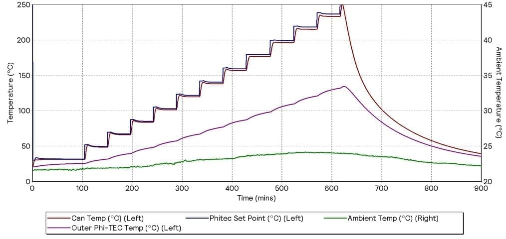
A primary use of adiabatic calorimetry can be to provide data for process development. It can quantify the thermal runaway potential of a chemical reaction process. The Phi-TEC I has been designed for this purpose. It has been developed to precisely and accurately measure very small changes in sample temperature to identify the onset temperature of a thermal decomposition or chemical reaction under adiabatic conditions. A key test protocol used to detect the onset temperature of thermal runaway is a “Heat-Wait-Search” plan. In such a plan, the sample and guard heaters increase in temperature in defined steps (Heat), holding each set temperature for a specified time to ensure thermal stability (Wait). During the Wait step, the system monitors changes in the sample temperature as a function of time, to identify if the onset of a thermal runaway has occurred (Search). An example of this test is shown in Graph 2.
The heat losses from any physical system increase with increasing temperature. The Phi-TEC I actively compensates for this to ensure adiabatic conditions are maintained. The Phi-TEC I is calibrated across the full operating temperature range of the system. This is done by using pre-calibrated Heat Loss Compensation (HLC) terms to calculate the increase in temperature needed from the guard heaters to maintain a constant sample temperature. Once the heat losses have been compensated for, the sample temperature is maintained at an extremely stable value. Any deviation in the sample temperature during the “Search” step that is greater than the user-defined detection threshold will cause the system to go into an adiabatic “Tracking” step. During this “Tracking” step, the thermal runaway or chemical reaction is held under adiabatic conditions, giving the user insights into the sum of energy released from the reaction, along with the ability to characterise the reaction and its kinetics, and provide vital safety data. On a Phi-TEC I, the detection sensitivity is as low as 0.02 oC/min (dT/dt).
As is best practice with all calorimeters, the Phi-TEC I needs to be used in thermally stable environments. The HLC terms are appropriate for a given external temperature and various environmental conditions such as air flow and humidity.
In this study, the impact on data quality from artificially changing the external environment was characterised. This study also reports on the use of an insulating jacket, which allows the Phi-TEC I to be used in thermally variable environments, whilst maintaining the expected system accuracy and sensitivity. It was therefore suggested that the influence of the environmental conditions on the sample temperature could be reduced while using this insulating jacket.
This insulation jacket was specifically designed to be fitted onto the current Phi-TEC I model. Because of this, both future and current end users will be able to utilize this insulation jacket to ensure the accuracy and reliability of their system.
Equipment and Methodology
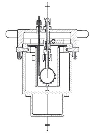
A Phi-TEC I underwent minor modification to install additional temperature measurement points. These points provided measurements of the ambient lab temperature, and an outer-wall temperature measurement of the Phi-TEC I oven. The outer wall temperature will highlight the thermal effects that the Phi-TEC I is subjected to during the experiments. No additional modifications were made to the Phi-TEC I to ensure it accurately represented an end user’s equipment. A Phi-TEC I’s test oven is shown in Figure 1.
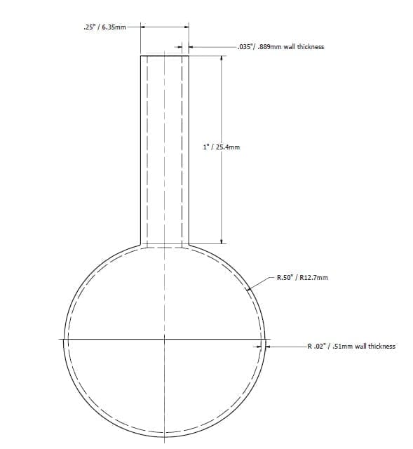
A HLC calibration was performed on a stainless steel (SS) test cell [1” diameter ¼” feed tube] with a blank liquid sample of 5 g of toluene. The test cell is shown in Figure 2.
The test cell was loaded with a blank sample of 5g of analytical grade toluene (Cas Number 108-88-3 (1)). Toluene was used for these experiments, as it would not undergo exothermic decomposition under the test conditions, and has a similar thermal mass to a real chemical test. Therefore, the Phi-TEC I would not be expected to go into “Tracking” mode in any of these tests.
Once the HLC parameters had been evaluated, a Heat-Wait-Search (HWS) test was conducted under stable laboratory conditions. The instrument was placed in a recirculating fume hood with minimal temperature fluctuation. This demonstrated that the HLC terms were appropriate, as the unit did not detect an exothermic event under these standard operational conditions. Once this was confirmed, the environmental conditions of the system were adjusted by significantly increasing the air flow over the system and thus increasing the heat losses from the system. This caused fluctuations in the outer wall temperature of the Phi-TEC I. This simulated the type of variation that a user might experience in a typical laboratory, due to (for example) air conditioning turning off at the end of the working day. This caused the induction of a premature “Tracking” step.
A thermal insulation cover was then installed on the Phi-TEC I to prevent the system going into “Tracking” mode due to the environmental variability. This jacket has been specifically designed for the Phi-TEC I, and comes in three, easy to install sections. Each section can be strapped into place via Velcro strips, reducing the time needed to install the insulation cover.
Results and Discussion
All results are shown graphically in this section. Unless stated otherwise, each graph has Experimental Time as the x-axis. Can Temperature (Red), Phi-TEC Setpoint (Blue), and Outer Phi-TEC Temperature (Purple) are plotted against the left-hand y-axis. The Ambient Temperature (Green) is plotted against the right-hand y-axis.
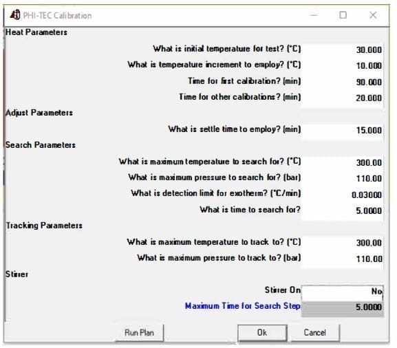
The Phi-TEC I was placed into a fume hood, and a calibration run on the ¼” SS test cell to define the HLC parameters. The conditions for the calibration test are shown in Figure 3, with the results plotted in Graph 1.
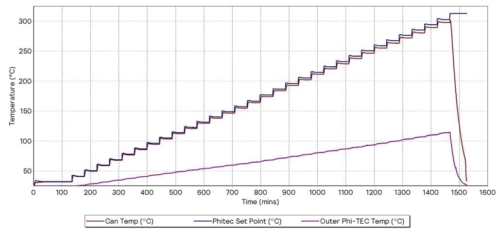
Graph 1 -Calibration of 1/4 ” SS Test Cell With 5G Toluene
From the calibration test, the following HLC terms were evaluated:
| Quality factor | 1 |
| Convection factor | 0.00018 |
| Convection exponent | 0.7 |
| Conduction factor | 0.016 |
| Radiation factor | 0.2 |
| Max correction | 1000 |
| Fixed offset correction | 0 |
Table 1: HLC terms used
For more understanding on the use of these HLC terms, and the equation that is used to calculate the “guard heater advance”, please refer to the Phi-TEC I “HLComp” Manual. (2)
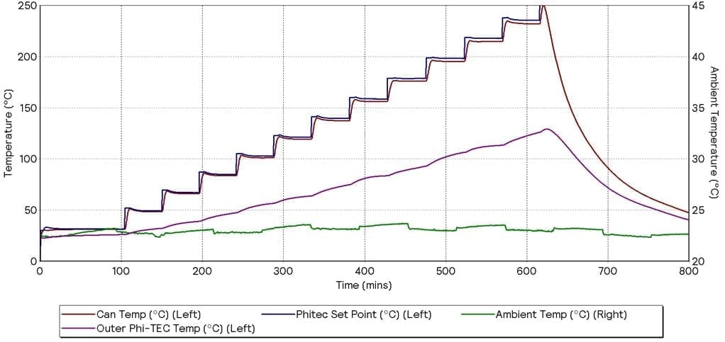
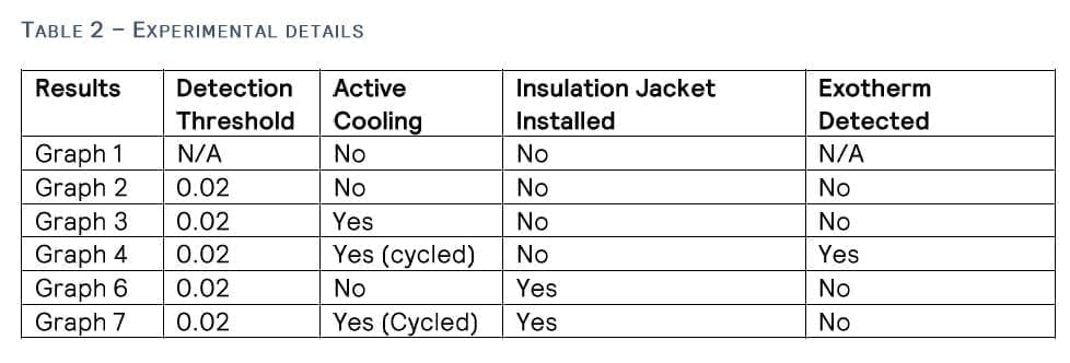
These HLC properties were adopted for the following tests. The first test had no additional cooling applied to the Phi-TEC I (Graph 2), and the next had additional cooling continuously applied for the full duration of the test (Graph 3).
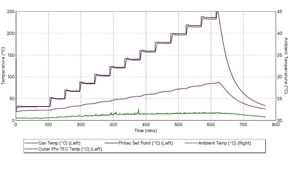 Graph 2 – HWS With No Additional Cooling
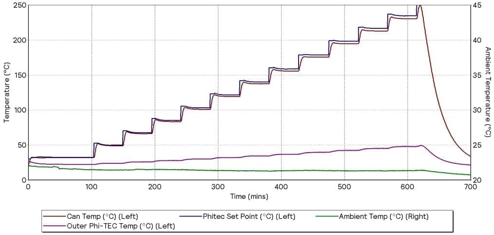
Graph 3 – HWS With Additional Cooling
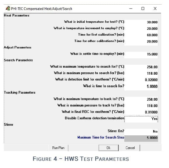
Both of these tests were defined by the HWS plan shown in Figure 4.
Neither of these experiments caused the system to go into Tracking mode, and thus no false detection of exothermic event took place. This demonstrates that the Phi-TEC I can operate in either cooled or uncooled conditions, as long as a stable external environment is continuously maintained.
In the next test, the cooling effect applied to the Phi-TEC I was turned on for one hour, and then off for the next hour. This was cycled hourly for the majority of the test and the results are in Graph 4. The effect of the active cooling can be seen in the ambient temperature (green) slightly fluctuating and the Outer Phi-TEC Temperature (purple) significantly fluctuating. Due to the changing external environment, the Phi-TEC I went into “Tracking” at the 450-minute mark.
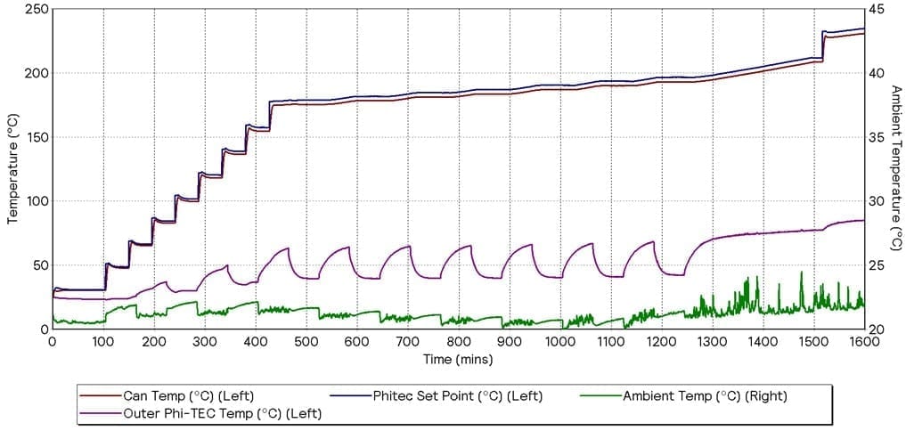
Graph 4 – HWS Cycling Additional Cooling
This is highlighted in Graph 5. It is shown that due to the changing environmental conditions, the Outer Phi-TEC Temperature is still stabilising, meaning that the heat losses are inconsistent. Because of this, the guard heaters over-compensate, which increases the sample temperature (red) – leading to false detection of an exothermic event. This would unnecessarily extend the experiment duration and could lead to incorrect conclusions due to the Phi-TEC I unnecessarily staying in the adiabatic “Tracking” mode. This highlights the need for an uninsulated Phi-TEC I to be placed in a thermally stable environment.
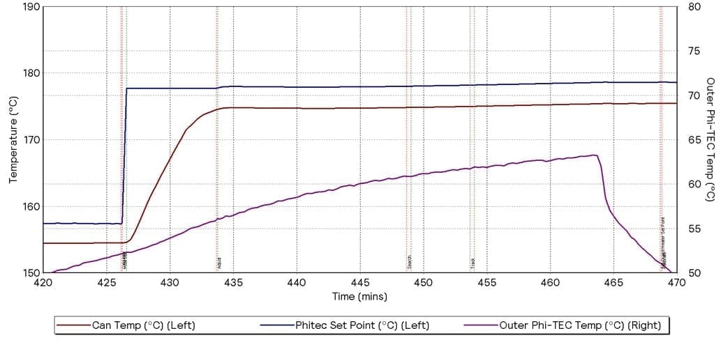
Graph 5 – Highlight Of Changing Environmental Conditions Causing Incorrect Detection Of Exothermic Event
To reduce the effect of the environmental temperature fluctuations, the insulation jacket was installed on to the same Phi-TEC I. Another calibration run was performed with the same parameters as displayed in Figure 1. This confirmed that no changes were needed to the HLC terms.
To prove this, another HWS test was completed with the parameters as set out in Figure 2. The results are shown in Graph 6. This result showed the Phi-TEC I did not enter “Tracking” mode. This was expected as the active cooling was not used for the duration of the test, allowing for constant environmental conditions.
Graph 6 – HWS With No Additional Cooling – Insulation Jacket Installed
The final test was with fluctuating cooling applied to the Phi-TEC I, while the insulation jacket was in place. The results from this are displayed in Graph 7. The ambient temperature (green) follows a very similar profile to Graph 4, showing that the active cooling was being cycled for the duration of the test. However, the Outer Phi-TEC Temperature (purple) is not fluctuating, and instead follows the Can Temperature, as seen in the other tests.
Graph 7 – HWS Cycling Additional Cooling – With Insulation Jacket Installed
As can clearly be seen from the results, at no point did the system enter “Tracking” mode, even with a detection threshold set as low as 0.02oC/min. This is understandable, as the unit is being effectively insulated. This insulating jacket enabling the system to be used in environments with moderate temperature fluctuations, without taking up additional bench space.
Conclusion
The aim of this study was to demonstrate that fluctuating environmental factors would induce a Phi-TEC I to incorrectly start a “Tracking” step. The unfavorable environmental conditions were accomplished by hourly cycling moderate active cooling to the system. This cooling is consistent with what could be experienced in a laboratory. This study also was designed to show that these effects could be mitigated with an insulating jacket.
It was also noted during these experiments that the system could retain the previous HLC terms for the ¼” SS test cell. On the basis of this data, it is expected that for a given test cell, no recalibration of the equipment is required when the insulating jacket is used.
During these studies, the effect of fluctuating external temperature was significantly reduced by use of the insulating jacket. At no point did the Phi-TEC I go into “Tracking” of an exothermic event after the insulation cover was installed. Thus, under these experimental conditions, the insulation cover eliminated false exothermic events.
Therefore, we recommend that the insulating jacket should be used in situations where the Phi-TEC I system will be placed in (potentially) thermally unstable environments to maintain the expected high data quality.
References
1 – Aldrich, Sigma. Analytical Grade Toluene. Sigma Aldrich. [Online] 14 Feburary 2020. [Cited: 14 Feburary 2020.] https://www.sigmaaldrich.com/catalog/substance/toluene921410888311?lang=en®ion=GB.
2 – H.E.L. Heat Loss Compensation Software Manual. Borehamwood : H.E.L Group, 04/09/2013. Vol. 1, 1.